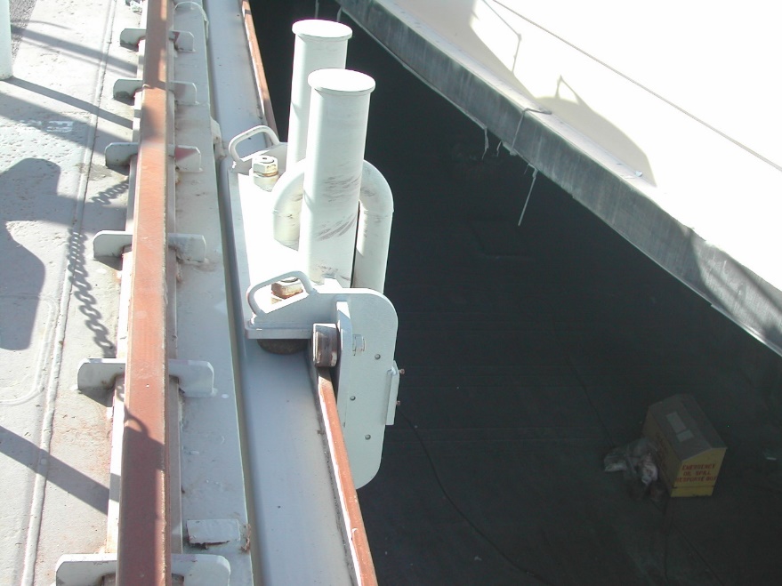
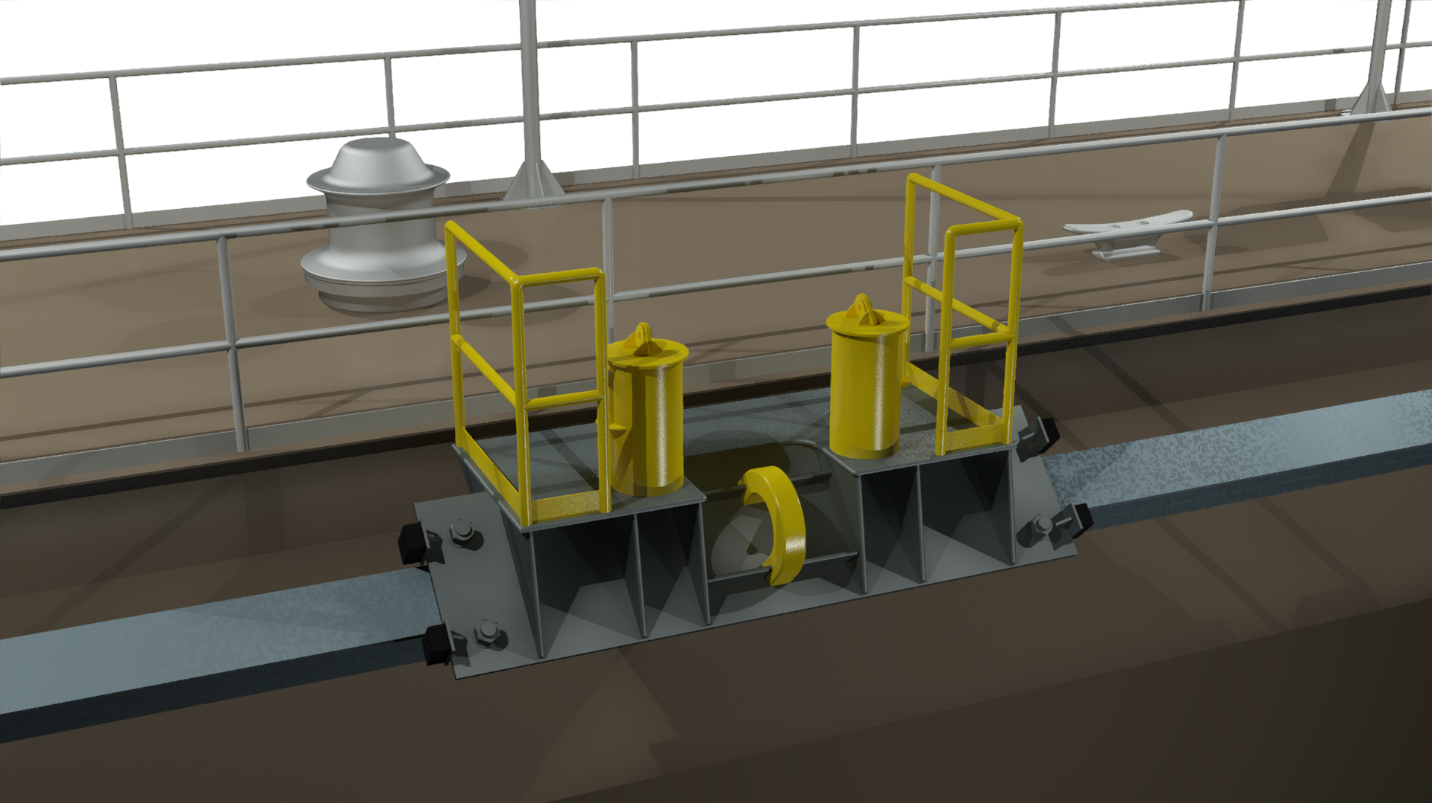
A “standard” trolley system utilizes a non-mechanical type trolley (aka “Dead” or “Slave” trolley) to maintain a constant static connection between the vessel being hauled and the trolley connected to the dock. The trolley acts more as a mobile mooring point or bitt that moves with the vessel as it is hauled in or out of the dock. An example trolley isometric is provided in the figure below:
Line handling personnel will have to initially secure the line, connecting the trolley and vessel. Once the lines are secured, port and starboard with only moderate slack, the vessel will maintain its position transversely in the dock as it is hauled longitudinally. The trolley will roll along the designed rail with the vessel and maintain a positive mooring connection as environmental forces such as wind and current act to displace or rotate the vessel. Line handlers will then only responsible for maintaining the excess tail of the mooring line as the trolley rolls down the dock.
Due to the nature of this non-powered trolley system, and the lack of mechanical force in the system, assistance is required from either auxiliary capstans or from tugs in order to bring the vessel into or out of the dock.Once the vessel is maneuvered, final positioning is typically accomplished using additional lines and capstans.
A typical procedure for trolley operations on a graving dock are illustrated below:
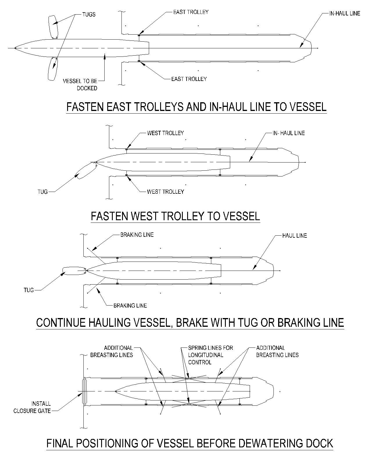
A typical procedure for docking using a standard style system on a floating dry dock is described as follows:
- All trolleys on both the port and starboard sides of the dock shifted to end where the vessel is to first cross the dock’s sill.
- Vessel assisted by tugs to sill of dock.
- As stern/bow of the vessel crosses the sill, all stop, and two trolleys (one per side) are mated up to bow/stern of vessel. Line tension is then equalized.
- Vessel assisted across sill and into dock by either capstans, winches, or tugs.
- If employed, as amidships of the vessel crosses the sill, all stop and a second set of trolleys mated up to amidships of the vessel. Line tension is then equalized.
- Vessel continues to be assisted into dock by either capstans, winches, or tugs.
- As stern/bow of vessel crosses the sill, all stop and final set of trolleys mated up to vessel. Line tension is then equalized.
- Vessel hauling continues until the vessel is in the final docking position. Minor adjustments can be made using additional manual lines or cable come-alongs
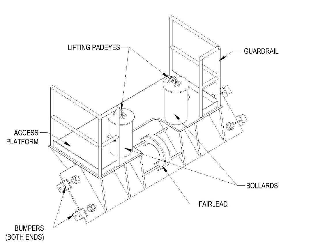
There are many different design variations of a non-mechanical type trolleys and in many cases can be custom designed for fit, function, and capacity on the dry dock.